Trial, meet error:

I’ve been working for about 6 months on finding a suitable silicone rubber material to use when making the keys for my beatseqr project. I started on this journey right after I’d set up my blacktoe cnc router. I knew I wanted a clear rubbery material to put in between the LED Tact switches on my circuit board for the user to push. This is a pretty well understood paradigm, so I figured there had to be a low-volume, relatively low-cost way to at least do some research into the feasibility of being able to do this. Of course you never know everything you need to know when you just start stabbing wildly at solving a problem that doesn’t have an obvious solution. So, below is a small sampling of the attempts I’ve made.
TAP Platinum Silicone

When I started, I thought I knew what I needed. A clear silicone rubber. Right? Should be easy to find. I didn’t really know what exactly to look for, but then I saw that TAP had one! I drove on down to one of my local TAP stores and was a little sticker shocked at the price. Oh well, one credit card swipe later, I was ready to test it out. The product is really simple to use. It’s a 1:1 mix ratio, so you pour parts A and B in equal amounts, mix it all up, and start pouring it into your mold. It’s super runny before it cures so it pours easily.
Once I had tested it out, I realized that there was a critical third qualifying attribute to the silicone that would ultimately win the day: hardness. Smooth-on has an excellent FAQ posted about this topic. It explains everything you need to know and has a printable visual aid. Ok, so with that new knowledge, I can see that this TAP silicone has a Shore hardness of A8, which explains why it feels like floppy gelatin. I’m going for a push button with some give, without being squishy. So this silicone was not going to work. (It did, however, come back later as an excellent mold making material, its intended use anyway.)
Smooth-on Sorta clear 40

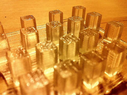
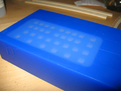
So while we were showing Beatseqr at the Bay Area Maker Faire 2010, I was able to locate the Smooth-on booth and discovered a couple of clear silicone rubbers that were MUCH firmer than the silicone I’d tried. Sorta clear 40, and Dragonskin 30. (Note that those product pages contain more than one shore hardness in the same product line!) I figured I’d go with the firmest one they sold, so I located a local dealer and bought a quart sized trial kit of Sorta clear 40. As you can see from the photo above, the optical properties are excellent with this product. However, after running a couple of test castings with this product, I discovered a fourth critical qualifying property that I’d need to consider: viscosity.

Sorta clear 40 is an excellent material. I really like it. It does, however, trap air bubbles… permanently, if you don’t do something about it. That something you can do is called “degassing”. Degassing essentially means that you use a vacuum chamber to forcibly remove trapped gasses, usually air, but sometimes other gasses depending on what you’re working with. Well, I didn’t have a degassing vacuum chamber, and the ones that I found when searching for them seemed to cost multiple hundreds of dollars on the low end, and thousands on the high end. Definitely not within my budget for this test.
I found an article explaining how to build one, so I did that. I’ll save the explanation for another post, but I managed to cut the price down from $800 down to about US$250. I’ve always been interested in different materials, and I knew I could use this degassing chamber for other stuff later, so I justified the cost and assembled the parts.
The viscosity of sorta clear 40 is pretty high, meaning, it does not pour like water. More like honey. Or taffy. The way you combine the 10:1 mix ratio parts is to open the canister of the part A liquid and scoop out 10 parts into a cup on a scale, and then add drops of part B to the mix until you reach the 10:1 ratio. I say “scoop” because the part A liquid is barely a liquid. If you hold the container upside down, it does not pour out. It’s perfectly happy to stay there without pouring at all. When you mix parts A and B together, it does become a somewhat pourable liquid, but before you get there, you have to stir stir stir for 3 minutes to get it fully mixed. Then the material has a bazillion air bubbles in it. So off to the degassing chamber it goes for several minutes, all while the “pot life” is ticking away. Pot life, meaning that you have a certain number of minutes after you combine the parts before they start to cure and solidify, so you need to work pretty quickly to get everything done once you start the process. So, out of the degassing chamber, and into the casting mold, quick!

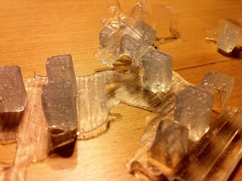
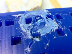
above, you can see the worst case scenario of rushing to get the silicone into the casting mold, and not being thorough about making sure all of the cavities are filled and big air bubbles are out. Not only does this produce an unusable finished product, it wastes time and money. 
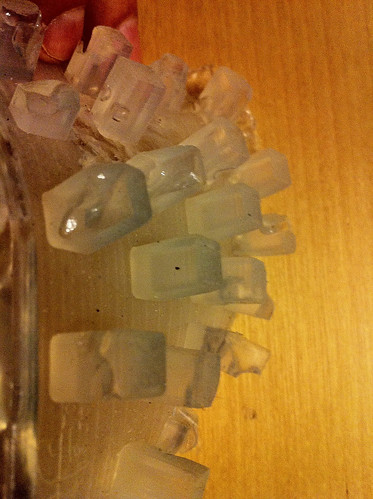
Above is a test I ran to mix, degas, pour, and then degas in the mold. It sorta worked. Small bubbles were reduced significantly, but big bubbles formed and by the time the silicone started setting up, they were trapped forever.
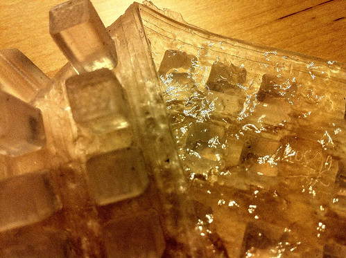
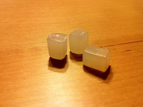
Above is another test I ran in a similar fashion. I got pretty good clarity by working faster and leaving more time for the silicone to sit in an uncured state in the mold, but while working feverishly to make sure all big bubbles were eliminated, I overworked the material past the pot life, and so the back of the flange is mottled and uneven. This might be usable, but seems like waaaay too much work to get it right every time.
Originally, the first beatseqrs had acrylic bar stock cut into rectangular shapes and hand sanded to be used as the button interface. The look and feel was pretty good, but the amount of work it took was too much for any kind of mass production, so I thought I’d try a casting acrylic to get the same/similar results without having to do so much hand work finishing. For all of the silicone castings, I am using machinable wax as the negative casting mold. Casting soft rubbery materials into a hard mold is fine, but… you can’t do that for rigid materials. So I made a “master positive” casting out of the TAP silicone, and then a silicone negative from that master positive. Actually, i did two. the first time, I didn’t adequately spray down the master positive with release, and silicone loves being cast on top of silicone, so I adequately destroyed the first silicone negative mold that I needed to do it again. The second silicone negative worked fine, and I was able to do the above casting in the casting acrylic I found at Michael’s.
Ok, BUT … when I went to do the acrylic casting, I discovered the downside to this material immediately. It basically smelled like a chemical factory took a crap, exploded, and died. And it stayed like that for upwards of 3 weeks. I asked a guy from Smooth-on about that and he said it sounded like it was a polyester casting material. Ok, so as pretty as it looks, I will definitely avoid using that again. The jury’s still out on rigid keys… Smooth-on has a material I may run some tests with, but maybe later if some customers dislike the silicone keys. So far, that hasn’t happened too much.
I had these silicone negative molds, and started looking around my garage. I noticed how nice and translucent hot melt glue sticks are. After I realized that silicone would more than withstand the heat, I did a test and got some interesting results. Maybe this is a good fast casting material in some cases. It’s relatively cheap and easy to work with. But… really… not what I was going for.
Enter the dragon. Smooth-on Dragonskin 30, to be precise. While at World Maker Faire 2010 in NYC, I got a great recommendation to try dragonskin 30. It seemed to have the right properties for this need:
1. translucent. Not transparent like sortaclear 40, but early tests indicate that LED light transmission is pretty good, which is what I want.
2. shore hardness A30, which is pretty firm. Not quite as much as sortaclear 40, but firm enough.
3. 1:1 mix ratio, so easy peasy mixing.
4. low viscosity, easy pouring. Less trapped air bubbles, should be easier to degas.
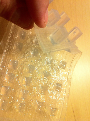
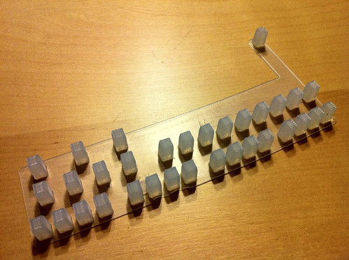
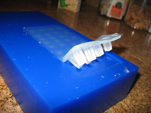
5. good working time and self leveling. Here, take another look:
The flange is super smooth. That lets it sit perfectly flat on the LED Tact buttons so they they’re all seated evenly. There are some air bubbles trapped in the casting, but that’s because I didn’t bother degassing the early tests. I’m confident that if I need to get more clarity in the final castings, degassing will go well because this silicone is so much less viscous than sortaclear 40.
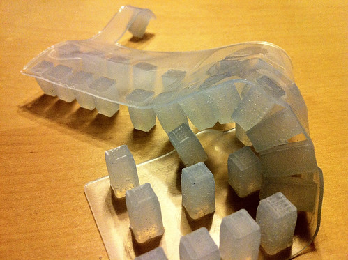
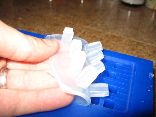
Full castings in the mold cavities. Awesome. Minimal hand-working to get it to that state. Since the material pours much more easily, it doesn’t need much coercion to fill all the nooks. I declare a winner! Dragonskin 30.
There are a few loose ends to tie up on this story, so maybe when I complete all of the research I want to do on this process, I’ll post up the results. I’m hopeful my market for beatseqr is just starting, and I’ll need to keep refining my products to meet demand. If that happens, I will have more to post.
UPDATE … it occurred to me that you might be interested in see what the casting mold looked like (or, one similar to the current one I’m using) and how the casting mold looks when it’s filled, and how the casting looks as it’s coming out of the mold, so here you go!

UPDATE 2: just a reminder to never leave your CNC program running unattended. I stepped away for one minute right at the end of this run, and KABLAM… ruined casting mold. I was lucky it was just wax!